
3D Ball Screw Part Model
$0.00
Our engineering team can customize any design.
File Formats:
- SolidWorks: SLDPRT, SLDASM, SVPJ
3D Ball Screw Part Model
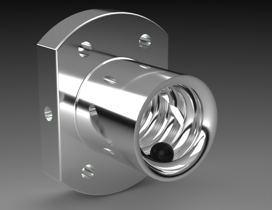
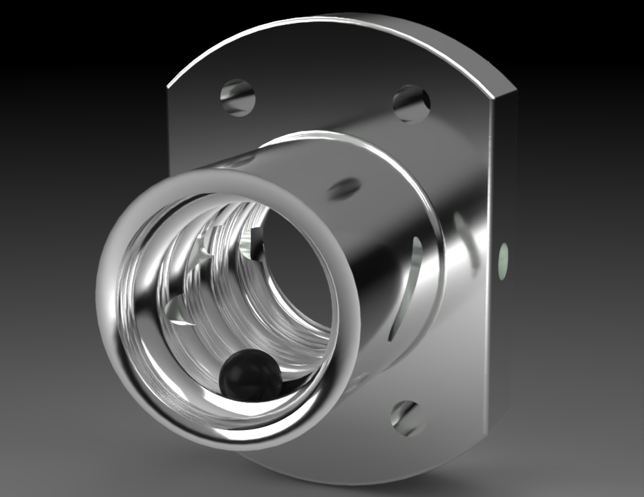
3D Ball Screw Part Model is a high-precision digital representation of a ball screw mechanism used for converting rotary motion into linear motion in CNC machines, automation systems, robotics, precision stages, and industrial equipment. This 3D model is ideal for mechanical engineers, machine designers, and manufacturers who require accurate geometry for design integration, motion analysis, and technical visualization.
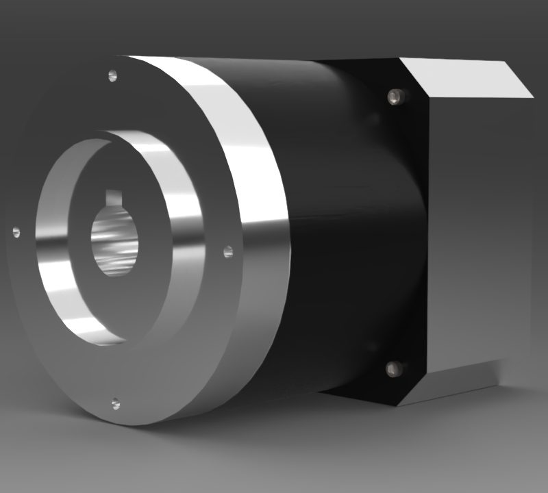
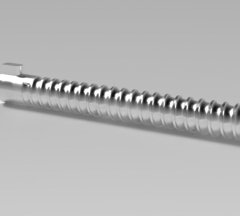
The 3D model typically includes the screw shaft with helical raceways, ball nut assembly, recirculating ball paths, end supports, and mounting interfaces. Dimensions and tolerances are modeled to reflect real-world ball screw configurations, making the model suitable for both engineering reference and high-quality rendering.
Key Features
-
High-accuracy 3D modeling of ball screw components
-
Realistic helical geometry and nut assembly detailing
-
Editable model for customization and sizing variants
-
Clean topology optimized for CAD, simulation, and rendering
-
Suitable for precision mechanical and automation applications
Applications
-
CNC machines and machining centers
-
Industrial automation and linear motion systems
-
Robotics and precision positioning equipment
-
Product visualization and exploded-view documentation
-
Engineering education and technical presentations
File Formats
-
STEP
-
IGES
-
STL
-
FBX / OBJ
-
Native CAD or 3D software formats (on request)
Using a Screw Part Model helps improve linear motion design accuracy, supports motion system validation, and delivers professional-grade technical and visual content.
Search Shop Section for more items to download for free.
| CAD Software Preference |
SolidWorks |
|---|---|
| Drafting & Modeling |
3D Modeling |
You must be logged in to post a review.

Reviews
There are no reviews yet.