
")


Output Air-Conditioning – CAD Models and Specifications
Overview
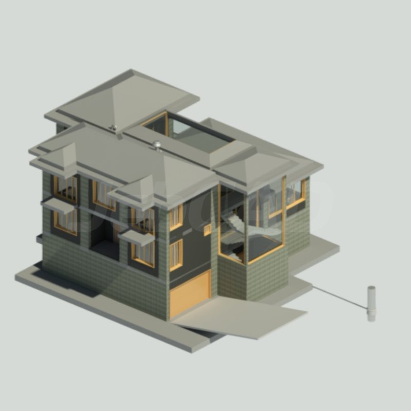
The Output Air-Conditioning CAD Models provide accurate 2D and 3D files for building design, mechanical engineering, and HVAC projects. Developed for both BIM workflows and fabrication layouts, these models ensure precise integration into residential, commercial, and industrial environments.
Technical Specifications
Dimensions
-
Wall-Mounted Unit: 800 × 250 × 300 mm (W × D × H)
-
Ceiling Cassette Unit: 900 × 900 × 300 mm (W × D × H)
-
Ducted System Unit: 1200 × 600 × 350 mm (W × D × H)
-
Parametric Models: Adjustable for custom HVAC layouts
Materials
-
Housing: ABS plastic or powder-coated sheet metal
-
Heat Exchanger: Copper tubes with aluminum fins
-
Fan System: Modeled centrifugal or axial fans
-
Filter: Washable mesh or HEPA filter assemblies
Functional Features
-
Airflow Capacity: 250 – 2000 m³/h (depending on model)
-
Cooling/Heating Modes: Integrated layouts for split or VRF systems
-
Electrical Integration: Power connections, PCB control panel, and remote interface included in CAD
-
Noise Control: Acoustic insulation modeled in larger ducted units
CAD Formats Available
-
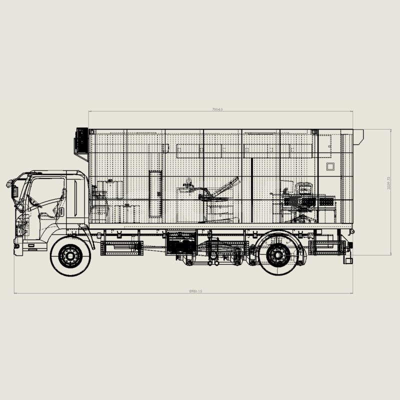
DWG (2D HVAC drawings)
-
RVT (Revit Families for BIM integration)
-
STEP / IGES (Mechanical and fabrication layouts)
-
STL (3D prototyping and visualization)
Applications
-
Residential: Apartments, houses, and small offices
-
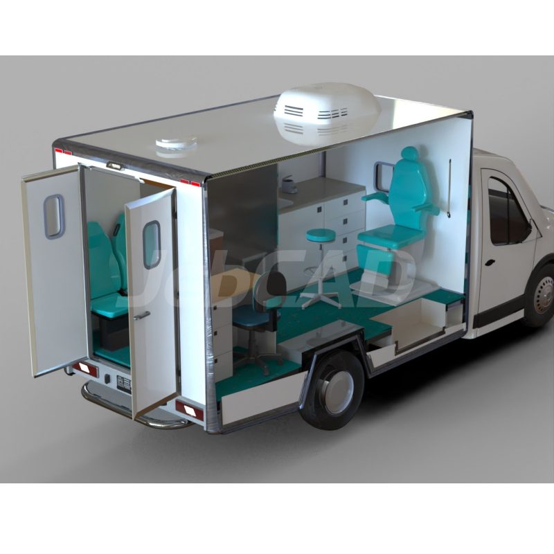
Commercial: Retail spaces, hospitals, schools, and offices
-
Industrial: Manufacturing halls, warehouses, and labs
Key Features
-
High-precision CAD models for HVAC planning
-
Parametric configurations for multiple air-conditioning types
-
BIM-ready for seamless architectural and engineering workflows
-
Detailed component modeling including fans, filters, and exchangers
See more on Shop.
You must be logged in to post a review.

Reviews
There are no reviews yet.