
")
Wheel rim
$0,00
Our Engineering team is opened to customize any design.
File Formats:
SolidWorks: STEP
Wheel Rim – 3D CAD Model
The Wheel Rim 3D CAD model is a precision-designed automotive component created for vehicle design, mechanical engineering, and manufacturing projects. This model represents a structurally accurate rim geometry suitable for passenger vehicles, light trucks, or custom automotive applications.
Designed with realistic proportions and detailed features, the wheel rim includes the central hub bore, bolt pattern area, spoke structure, and outer barrel profile. The clean and parametric CAD structure allows easy modification of diameter, width, bolt circle pattern, and offset according to project requirements.
This model is ideal for automotive engineers, product designers, fabrication workshops, and students working on vehicle assemblies, simulations, or visualization projects.
Technical Datasheet
General Specifications
-
Component Type: Wheel Rim
-
Category: Automotive / Rotational Component
-
Design Type: Alloy / Steel Rim (configurable)
-
Mounting Type: Multi-bolt hub connection
Dimensional Parameters (Customizable)
-
Rim Diameter: 13” – 22”
-
Rim Width: 5” – 12”
-
Bolt Pattern (PCD): 4×100, 5×114.3, etc.
-
Center Bore Diameter: Configurable
-
Offset (ET): Adjustable
Design Features
-
Detailed spoke geometry
-
Precision bolt hole pattern
-
Accurate hub mounting interface
-
Optimized structure for strength and balance
-
Parametric and editable CAD model
File Formats
-
SLDPRT / SLDASM
-
STEP
-
IGES
-
DWG (2D optional)
Applications
-
Automotive design projects
-
Wheel manufacturing preparation
-
Vehicle assembly simulation
-
Mechanical engineering education
-
Rendering and visualization
Search more related products on Shop section to download for free.
You must be logged in to post a review.
Related products

Blood Donation – 2D Design
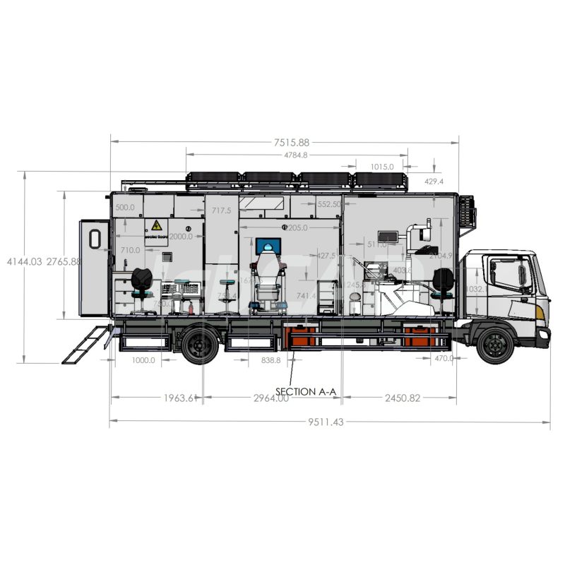
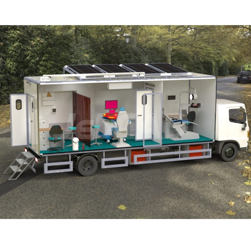
Dental Clinic – 2D Design
Reviews
There are no reviews yet.